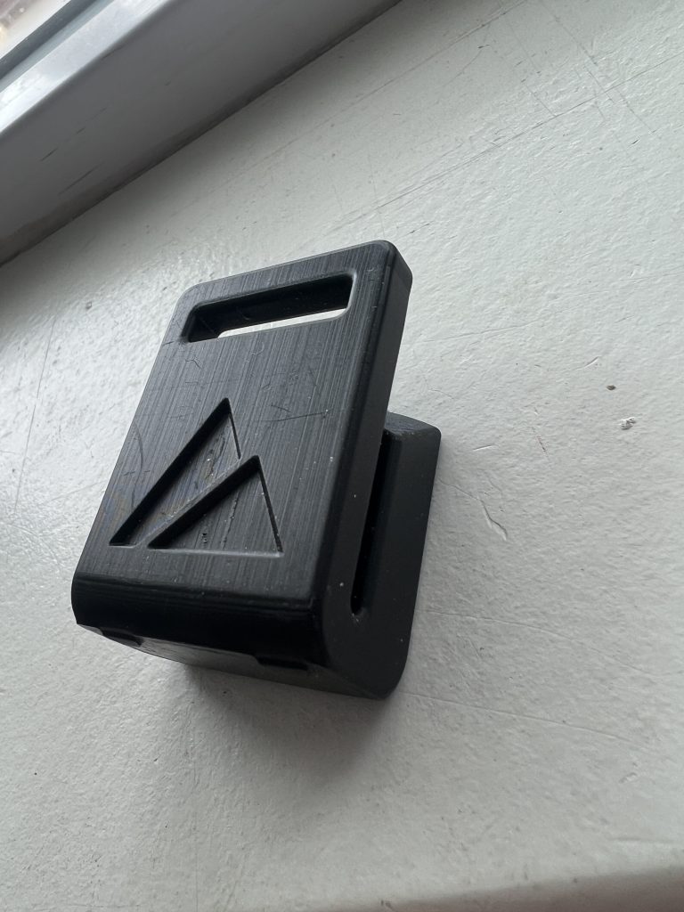
A customer sent us a bracket last month that had been designed, clearly, by someone who had spent a career designing for injection molding. Uniform wall thickness throughout. Draft angles on every vertical face. Generous radii in the corners, ribs where a molded part would need them to keep from sinking. It was a well-designed part. It just happened to be well-designed for a process we were not going to use.
None of that work helps a printed part, and some of it actively costs you. That bracket is the rule, not the exception. Most parts that come to us for additive arrive carrying the habits of the process they were originally drawn for. Unlearning those habits is where the real value of design for additive manufacturing, or DfAM, actually lives.
The habits molding burned in
Injection molding is a brilliant process with strict rules, and good designers internalize those rules until they stop noticing them. You hold wall thickness uniform so the part cools evenly and does not warp or sink. You add draft — a slight taper on vertical walls — so the part releases from the steel. You avoid undercuts, because anything that traps the part in the mold means a side-action and a more expensive tool. You design around a parting line and around where the gate and ejector pins will sit.
Every one of those rules exists to serve the mold. A printer has no mold. It does not care about draft, does not need to release a part from steel, and has no parting line. Carry the molding rules onto a printed part and you are paying a tax to a machine that is not even in the building.
What additive lets you stop doing
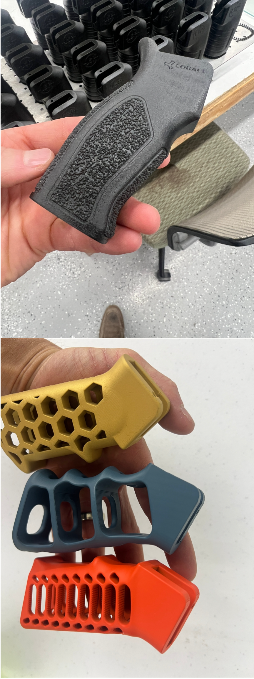
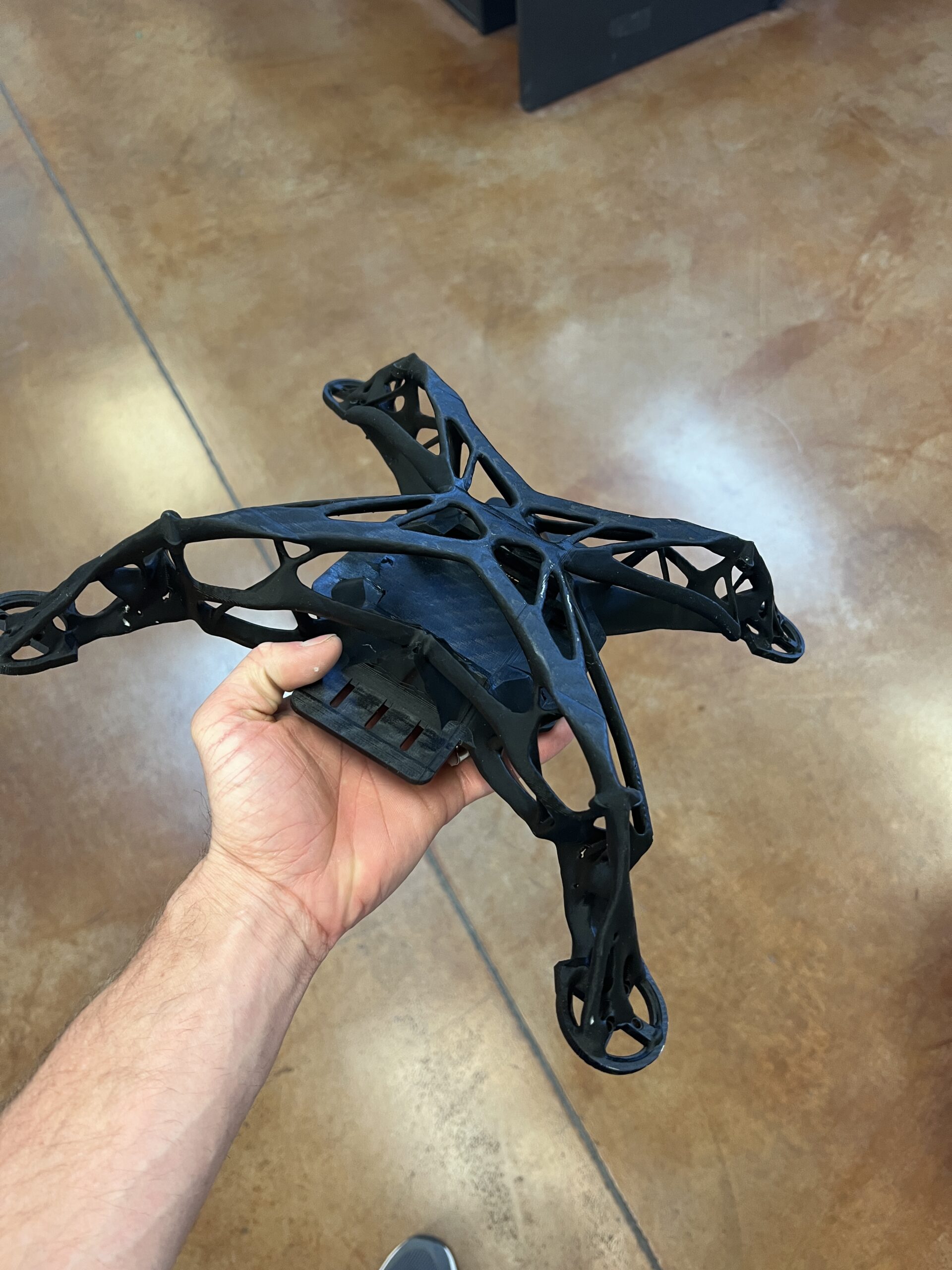
The freedom runs the other way. A printer builds a part up in layers, so geometry that is expensive or impossible to mold is often free to print. Undercuts cost nothing. Internal channels — cooling lines, fluid paths, passages that follow a curved surface — can run through the inside of a part where no drill could reach. Wall thickness does not have to be uniform; you can put material where the load is and leave it out where there is none. You can hollow a part and fill it with a lattice, an internal latticework that holds strength while cutting weight and material.
The mental shift is to stop asking “how would I mold this?” and start asking “what does this part actually need to do?” When the manufacturing constraints fall away, the part you draw starts to follow the function instead of the process.
Part consolidation is the real prize
The highest-value move in additive is not any single geometry trick. It is consolidation — collapsing an assembly of several molded pieces into one printed part.
A luxury watchmaker recently showed a case printed as a single continuous structure, the kind of thing that would normally be machined and assembled from several components. The headline was the look; the lesson was the count. Every part you design out of an assembly is a part you do not have to make, inventory, inspect, and join. A bracket-and-housing that used to be six pieces and a dozen fasteners can become one print. That is fewer line items on the bill of materials, less assembly labor, fewer fasteners to loosen, and fewer joints to fail in the field.
This is the part of additive that shows up on an operations report, not just a CAD screen. Assembly time is headcount. Fewer components mean a shorter, more reliable supply chain for that part. When we look at a printed assembly, the first question is almost always how many of these pieces can become one piece. It is usually more than the customer expects.
Where the freedom bites back
Additive is not a blank check, and pretending otherwise is its own kind of trouble. The process has rules of its own; they are just different rules. Overhangs past a certain angle need support structures, which take material and post-processing to remove and can mark a surface. Orientation on the build plate matters — it drives strength, surface finish, and how much support you burn. And printed parts can be anisotropic, meaning they are stronger along the layers than across them, so you orient the part with the load path in mind.
Spencer has a line for this: design for the process, not against it. It is the same discipline molding demands, pointed at a different machine. You are not escaping constraints by printing. You are trading a known set for a newer one — and the newer set buys you geometry the old one never could.
Leave the draft angles in molding
The best printed part rarely looks like the molded one it replaced. It has fewer pieces, thinner walls where it can, material concentrated where the load is, and features no mold could have produced. If your CAD still has draft angles on a part you are going to print, that is not really a problem — it is a signal. There is design freedom on the table you have not picked up yet, and usually money sitting right next to it.
Ready to see what your part would cost? Upload a CAD file for an instant estimate, see what we run on our capabilities and materials pages, or talk to a real person about your project.