Every few weeks a drawing lands in our inbox with ±0.05 mm stamped on every dimension. The title block says the part used to be injection molded, and the tolerances came along for the ride. Nobody ever measured the old parts to check whether they held that number. The assembly worked, the drawing survived, and now that same ±0.05 mm is about to make a 3D printing quote look worse than it should.
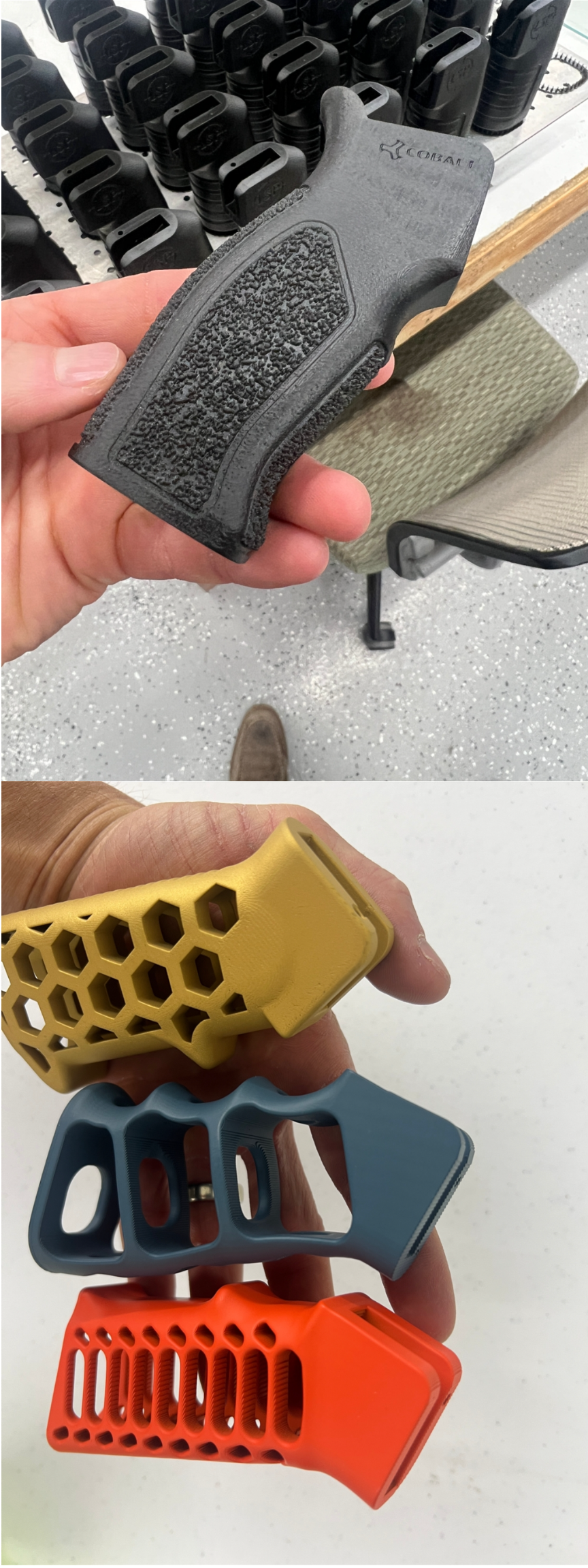
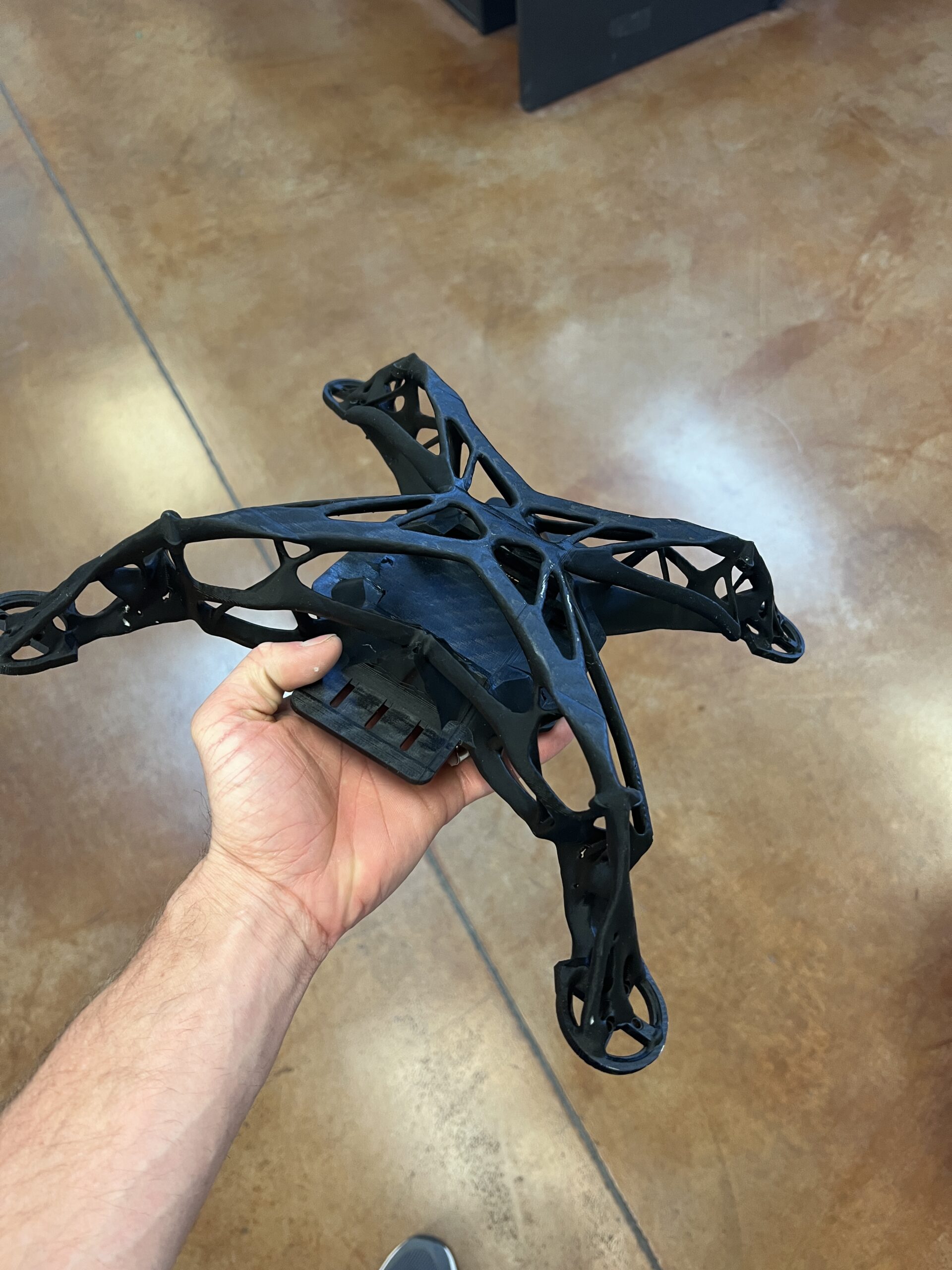
3D printing tolerances are the first thing engineers ask us about, and the internet answers the question badly, because most published numbers come from prototype shops printing one part at a time. We mass produce on SLA LCD printers — SLA (stereolithography) means liquid resin cured layer by layer with light, and the LCD is the mask that shapes each layer. Thousands of parts a day, every day, and production changes the answer. Here are our real numbers and what moves them.
Tolerance is three different numbers
When someone asks “what tolerance can you hold,” they usually mean one of three things, and the three get tangled together constantly:
- Layer height — the vertical resolution of the print. We run 100 microns for most production work, 50 microns where layer lines need to be hard to see, and lower microns for really fine work. This number describes surface finish far more than it describes accuracy.
- Dimensional accuracy — how close a printed dimension lands to the nominal in the CAD file.
- Feature tolerance — what the drawing demands of one specific dimension, hole, or mating surface. This is the one that costs money.
A part can carry crisp 100-micron layers and still miss a bore diameter because of resin shrink or a bad orientation choice. Keep the three separate and every conversation about accuracy gets easier.
The real numbers, by part size
Size class moves the tolerance band more than any other single factor. A bigger part means more resin, more shrink, and more thermal movement across the build. These are the production bands we quote from:
| Part size | Process | Typical tolerance band | Common layer heights |
|---|---|---|---|
| Small — under 6″ longest dimension | SLA LCD resin | ±0.1 to ±2.0 mm | 100–250 µm |
| Medium — 6–20″ | SLA LCD resin | ±0.5 to ±5 mm | 100–250 µm |
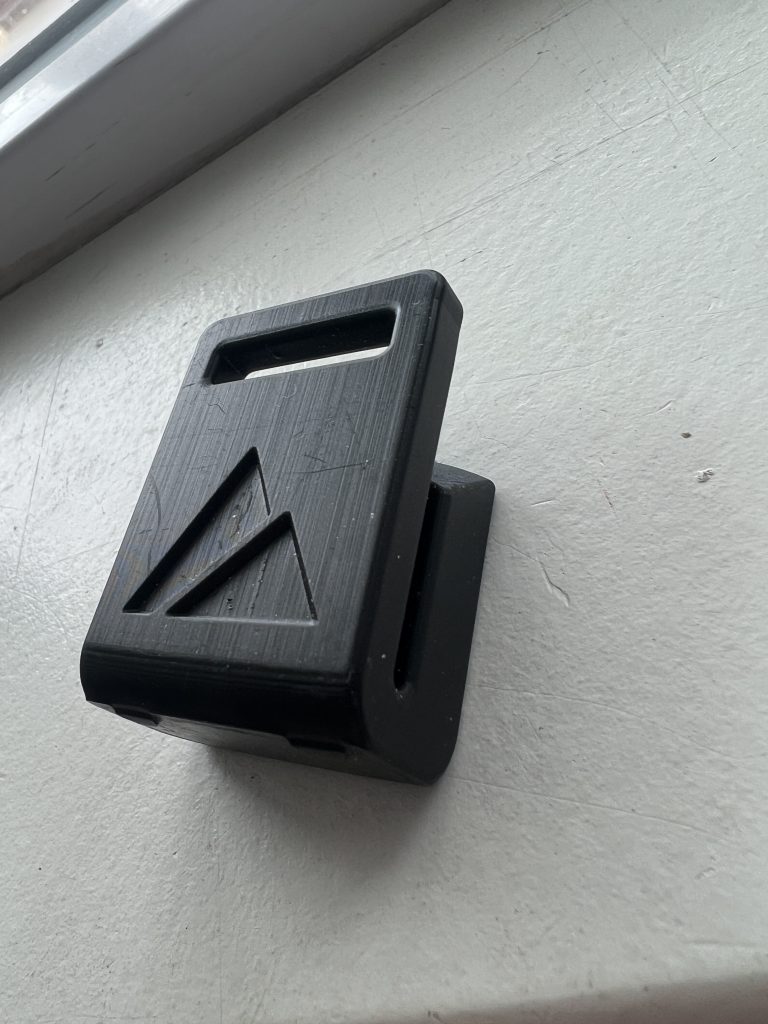
Those bands are wide on purpose. Where your part lands inside them is a geometry question, and most well-designed small parts hold far tighter than the top of the band. The binocular tether clips we run for Alaska Guide Creations live nowhere near ±2 mm, because nothing about their geometry pushes them there. The band exists because a tall, thin, unsupported wall and a short stubby boss are different animals on the same printer.
What moves you inside the band
- Orientation. A dimension built across the XY plane of the screen holds tighter than one built up the Z axis through hundreds of layer transitions. We pick orientation for the critical dimension first and let the rest of the part follow.
- Supports. Surfaces grown on support structures carry witness marks and slight pull. Critical faces should point away from supports, and the best production parts are designed to print with no supports at all.
- Cross-section. Thick solid sections hold heat and shrink more as they cure. Uniform walls behave. Big resin masses wander.
- Resin choice. Every formulation shrinks a little differently. DL110, a rigid high-impact resin we print daily, is predictable for us because we have run millions of parts in it and tuned the process around its behavior.
- Post-processing. Parts keep moving slightly through wash and post-cure. A dimension measured twenty minutes off the plate tells you less than the same dimension measured the next morning.
None of this is exotic. It is the same conversation a machinist has about tool deflection, or a molder has about gate location, moved to a different machine.
Tolerance the dimensions that matter
Blanket tight tolerancing is lazy drafting, and it costs real money in every manufacturing process. Additive just presents the bill faster. When every dimension on a drawing carries ±0.05 mm, we have to quote as though every dimension will be inspected to it: slower layer heights, restrictive orientations, maybe a fixture, maybe 100% inspection instead of sampling. The part price can double to protect tolerances the assembly never feels.
The honest version of most drawings has two or three dimensions that matter — a bore that seats a bearing, a snap fit, a mating face. Call those out, and let everything else ride on a general note like ±0.5 mm. When a critical dimension genuinely needs to be tighter than the printed process holds, say so early. Sometimes the answer is a quick machining pass on that one bore while the rest of the part stays cheap. Sometimes the answer is that additive is the wrong process for the part, and we would rather tell you that at the quote stage than after first articles.
How to put it on the drawing
If you want a quote that reflects what the part actually needs, send us:
- A general tolerance note that matches reality. ±0.5 mm covers most small consumer and industrial parts.
- Explicit callouts on the two or three critical dimensions only, with a sentence about what each one mates to.
- A photo of the assembly. It answers questions a paragraph of notes never will.
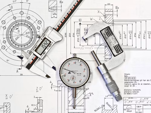
- Your measurement method. A dimension checked with calipers and a dimension checked on a CMM (a coordinate measuring machine) are two different conversations.
- Whether the old parts were ever measured. If molded parts held ±0.4 mm for ten years while the drawing demanded ±0.1, the drawing is negotiable.
We wrote a longer piece on what to send us before the CAD file, and if the part is still being designed, our DfAM (design for additive manufacturing) basics guide covers the geometry side of holding tolerance.
The calipers do not care about the title block. They close on one dimension, the one the bearing seats into, and the assembly either goes together or it does not. Spec that dimension like it matters and let the rest of the part be easy.
Easy parts are cheap parts.
Ready to see what your part would cost? Upload a CAD file for an instant estimate, see what we run on our capabilities and materials pages, or talk to a real person about your project.