
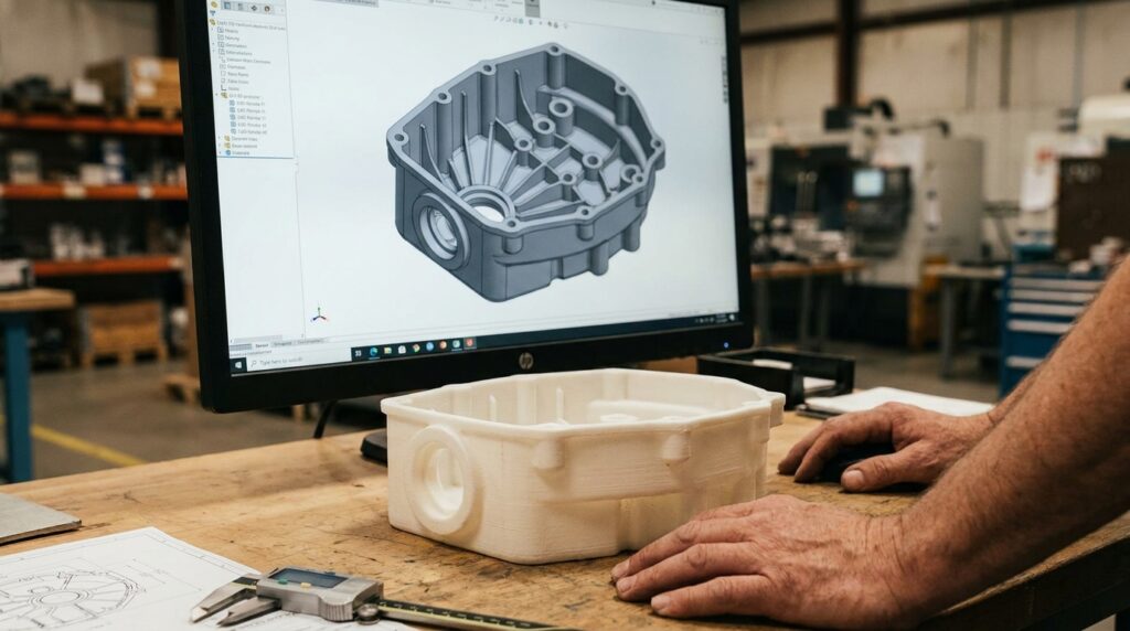
Most weeks a CAD file lands in our inbox that was drawn for injection molding. Clean surfaces, thoughtful ribbing, bosses where the fasteners go, a molded-in living hinge on the lid. The engineer who sent it has done this a hundred times for a mold. The problem is, they’ve asked us to print it.
This is the moment we start asking a different set of questions than the ones the CAD was designed to answer. The engineer didn’t do anything wrong — they designed for the process they were trained on. Design for Additive Manufacturing (DfAM) — the practice of shaping a part specifically so it prints well — inverts a lot of what CNC and injection molding taught us. If you’re new to additive, here’s the short version of what we look for when your file crosses our desk.
One anchor before we go further: this post is about the two processes we run daily at Merit3D — SLA (stereolithography, including the LCD variant our Photocentric Magnas use) and SLS (selective laser sintering of nylon powder). A lot of internet DfAM advice is written for FDM (fused deposition modeling — extruded plastic filament, like a desktop Prusa or Bambu). FDM parts have real Z-axis weakness because the layers are mechanically stacked strands. SLA and SLS parts bond chemically or by full-material fusion between layers and are much closer to isotropic. That single fact changes several of the design rules people assume are universal.
Build Orientation Is a Design Decision — Just Not for the Reason FDM Taught You
If you’ve read FDM DfAM guides, you’ve read that layer lines create anisotropy and the Z axis is the weakest. That’s true for FDM. It’s much less true for SLA and SLS. Photopolymer resin crosslinks chemically across layer boundaries during cure, and post-cure closes most of what’s left of the seam. Sintered nylon flows and fuses across the powder bed while the laser is passing — the layer boundary essentially disappears at the material level. A properly-processed SLS or SLA part behaves close to isotropic for most real-world loading.
So on our machines, build orientation is a design decision — but it’s usually not a strength decision. It’s a surface-finish decision, a support decision, a dimensional-accuracy decision, and a nesting decision. Downward-facing surfaces (where supports attach in SLA) come off rougher than upward-facing ones. Vertical walls in SLS pick up a slight stair-step texture from the layer boundary; horizontal top surfaces polish out cleaner. Parts near the edge of the SLS build chamber can shrink slightly differently than parts near the center. All of that matters for a production run.
The question we ask a new customer file is: which face is customer-visible, which face has a critical tolerance, and where are the mating surfaces? Tell us that, and we’ll orient the build so the finishes and dimensions land where you need them. You don’t have to specify orientation in your CAD.
Overhangs and Supports Leave a Fingerprint
On SLA, anything that hangs into space at a shallow angle needs a support structure underneath it while it prints. The rule of thumb is 45 degrees — steeper than that, the part holds itself up; shallower, and it needs help. Supports get removed after the print, and where they attached, they leave a witness mark: a rougher patch of surface finish, sometimes a tiny nub.
SLS is more generous — the unsintered powder around the part is itself the support, so overhangs and internal geometry that would need supports on SLA come out clean on SLS. You still care about part-to-part contact inside the powder cake (packing density affects thermal behavior) but you don’t have witness marks. This is one of the reasons a part that’s hard to make on SLA is sometimes trivial on SLS.
Injection molding leaves witness marks too — parting lines, ejector-pin marks, gate scars. The DfAM version of that awareness: if a face has to be A-side clean, tell us which face and we’ll pick the process (or the SLA orientation) so the supports don’t land there. Chamfers and small fillets on downward-facing edges also reduce the SLA support burden.
Wall Thickness Has a Floor and a Sweet Spot
Most CAD-for-injection-molding files come in with uniform walls around 2 to 3 millimeters. That’s a habit worth keeping — thin, uniform walls print well and cure evenly. But the floor varies by process. LCD 3D printing (also called MSLA — a resin process where a masked LCD screen selectively cures each layer) can technically hit 0.5 mm walls, but those tend to warp during post-cure. SLS is more forgiving but has its own minimum feature size around 0.7 to 0.8 mm before you start to lose the feature to sintering resolution.
The workhorse target for production additive parts is 1.2 to 2 mm walls. Thicker wastes material and print time. Thinner rolls dice on warp, cure gradient, and post-processing survival. If you have a structural wall below 1 mm, flag it. We’ll either thicken it or route the part to the process that handles it best.
Holes Come Out Small, Threads Come Out Rough
Hand a CNC shop a 6 mm hole and you get a 6 mm hole. Hand an additive shop the same file and you get something slightly smaller. Resin shrinks as it cures. Sintered nylon has its own dimensional behavior as the powder cake cools. The exact amount varies, but 0.1 to 0.2 mm undersize is a safe planning number.
Two options. Model your holes 0.1 to 0.2 mm oversize if they’re clearance-only. If a hole needs to be precise — a bearing fit, a dowel pin, tighter than about 0.1 mm — design a drill-ready pilot and plan to ream in post. Threads, especially small ones, are almost always stronger when you print smooth and tap after. A heat-set or press-fit insert is another common approach.
Text and Small Features: Recess Over Emboss
Everyone wants their part number, revision, or logo molded into the surface. On both SLA and SLS, recessed text prints noticeably cleaner than raised text. Raised text fights the layer resolution on every character and picks up support witness marks on SLA; recessed text lets the machine cut into a flat surface and leaves crisp edges. Target 0.3 to 0.5 mm depth and 2 mm minimum character height. Sans-serif fonts read better than serifs — the tiny serifs disappear at print resolution.
Fits, Clearances, and Living Hinges
If your assembly has two parts that need to slide, snap, or hinge together, the clearance you’d design for injection molding is not the clearance you want for additive. A snap-fit (a plastic feature that flexes to engage a mating feature and locks in place) needs enough room to actually flex. A living hinge (a thin section of material designed to flex repeatedly without breaking) can work in SLA and SLS in essentially any orientation — the near-isotropic behavior means the layer direction isn’t a failure axis the way it is on FDM. What matters is the geometry: a hinge section around 0.3 to 0.5 mm thick, generous fillets where the flex zone meets the thicker walls, and a material that tolerates repeated strain (PA12 in SLS handles it well; standard photopolymer resins less so — flag it and we’ll pick the material).
The safe starting clearance between mating additive parts is 0.15 to 0.3 mm. Tight enough to feel positive when they engage; loose enough that resin shrink or powder-cake variation doesn’t leave you with an interference fit. Print-in-place mechanisms — hinges, chains, ball-and-socket joints that come out of the machine already assembled — are one of the small joys of additive, but only if you leave the right gap.
Consolidation Is Where Additive Actually Wins
The DfAM parts that make an operations team happy eliminate an assembly step. A housing that used to be four parts, six fasteners, and a gasket becomes one printed piece with the bosses, clips, and seal groove integrated. Unit cost is higher, but total landed cost — accounting for assembly labor, the fastener BOM, and five separate SKUs in inventory — goes down.
This is the geometric freedom additive is famous for, and it’s real. Internal channels a CNC tool can’t reach. Lattices that reduce weight without sacrificing stiffness. Undercuts (features that would trap a mold) that are trivial to print. If you’re designing specifically for additive, draw the assembly you want, not the four pieces you’d have made before.
A Note on What Not to Do
Most of the online DfAM advice is written for FDM — layer-line strength, Z-axis weakness, brim/raft rules, support crosshatching. That guidance keeps a hobbyist from wrecking a print on a $500 machine, and it’s genuinely useful for FDM. It’s mostly wrong for production SLA and SLS. If you find yourself thickening a wall to survive Z-axis loading on our machines, or orienting a living hinge to align with layer lines, you’re solving an FDM problem we don’t have.
Production LCD and SLS machines also have different resolution, thermal behavior, and material chemistries than desktop machines in the same nominal category. A wall that works fine on a Formlabs Form or a benchtop SLS sample can misbehave on a Photocentric Magna running at production light intensities. When in doubt, ask the shop.
The Takeaway
DfAM isn’t a rulebook. It’s a way of asking the file a different set of questions. Where is the load going? What does the customer touch? Where do the supports land? Which features can we consolidate? The engineers who send us the best-printing parts on the first try aren’t the ones who’ve memorized every rule. They’re the ones who send us the file with a note that says here’s how it gets loaded, here’s the face the customer sees, here’s the tolerance that has to hold — and let us do our job.
If you’re moving a part from CNC or injection molding into SLA or SLS for the first time and want a second set of eyes on the CAD, send the file over.
Ready to see what your part would cost? Upload a CAD file for an instant estimate, see what we run on our capabilities and materials pages, or talk to a real person about your project.